Saturday, January 20, 2007

Fried Duron key fob

Fried Duron key fob by taw - front (CC-BY-SA)

My CPU got fried again. It was pretty old, and I have replacement hardware lying around, so it's not a big loss. The last time it happened (like 2 years ago), I forgot to mention that I want the dead CPU, so they threw it away. Not this time!

Fried Duron key fob by taw - back (CC-BY-SA)

That's something that I always wanted to have - a key fob made of my own CPU.

I used plain drill to make a hole. I made it in a place where there was no pin. That wasn't the best idea, as the hole is far from the edge, and it's harder to pass the keyring through it. If any more CPUs fry at me, I'm going to remove a pin near the corner and make a hole there.

Friday, January 19, 2007

README file for ipod-last.fm bridge

Sweet Dreams by Gui, o gato from flickr (CC-NC-ND)
I just uploaded a new release of iPod-last.fm bridge. Changes are a README file, copyright notice (MIT-style "do whatever you want"), and tweaks to the "fake songs" algorithms for more realistic results (it's still off by default).

It can be downloaded from the usual location.

If you have any questions, don't hesitate to ask.

Friday, January 12, 2007

Hello world of Chinese drawing


Non-computer art is fun. Unless someone's committed to spending rest of their life getting better at it, it's best just to accept that everything they make is going to suck big time. Have you accepted it already too ? Great, now we can have plenty of fun together.

A few days time ago, I got a 15 EUR special sale Chinese Drawing intro kit at Empik. It includes a solid ink bar, an inkstone, 3 small tubes of color paints (lemon yellow, cobalt blue, carmine), some rice paper, a CD with Chinese pop music, and a booklet with short tutorial and some pretty pictures.

Today I finally ripped the CD, and started drawing. Now, I actually tried something similar once or twice before, but back then my only idea was "Wow, this paper about converting 3D scenes into sumi-e-like paintings is so cool, I guess I'll just start drawing one without getting any more tutorials".

Other than that, this is my hello world. Like all hello worlds, it doesn't represent anything, I was just trying to get some idea how materials react. It's less trivial than I thought to handle ink and water right. From what I can tell, the bird-like thing and the moon-like thing suck most. The bamboo are kinda nice, especially since that's the first time I've ever drawn any.

Why the heck am I posting it to my blog instead of just trashing it ? In the future, it's going to be a great feeling to look back and see that I used to suck a lot more than I do now.

If you want to comment how bad it is, or anything like that, just go ahead. Getting bashed is a pretty good way of improving.

Friday, January 05, 2007

Blinkenlights, part 3 - wires

~How sweet is this? by *Sage* from flickr (CC-NC-ND)
When I started to think about electronics, I didn't spare much thought for the wires. The ICs (integrated circuits), the diodes - they were interesting. But wires ? What could possibly be interesting about them ? And in any case, number of wires is pretty much determined by number of wired elements - something like one wire for each two pins. Anyway, it's boring, boring, boring.

So when I made design decisions for the TTL CPU, I had two criteria:
  • Number of ICs
  • Number of things that can go horribly wrong and fry the ICs

In retrospect, I should have thought about wires too. But let's start with a simple example - a register file read port.

A register file consists of some small amount of memory, and a few ports. There are two kinds of ports. Write ports, that let you write to the memory, and read ports that let you read from the memory. Most register files have 1 write port and 1-3 read ports. For simplicity, let's just design one read port for a straightforward register file.

First - the memory. It's pretty common to simply use 8 8-bit D flip-flops. The read port is going to get the number of port to be read as a 3 bit number.

This means the read port has 64 input wires from memory, 3 input wires for address, and 8 output wires for the data.

But first, some explanations.

A 2-input multiplexer is a device that gets 2 input wires, 1 select wire, and outputs to 1 wire. If select is high, it connects the first input to output. If select is low, it connects the second input to output. Multiplexers are very useful, so they also make ones that can handle more signals. A 4-input multiplexer has 4 input wires, 2 select wires, and 1 output wire. An 8-input multiplexer has 8 input wires, 3 select wires, and 1 output wire. These three are common. Bigger multiplexers or not-power-of-two multiplexers aren't made for practical reasons.

A three-state driver is a device that gets N input wires, 1 enable wire, and N output wires. If enable is high, input and output wires are connected (first input to first output, second to second and so on). If enable is low, input and output is simply disconnected. It's called "three-state" because its outputs can be low, high, or disconnected; not just low and high like in most ICs.

Probably the simplest way of building a read port is using 8 8-input multiplexers (74LS151), one for each input. Each of them gets 3 address wires, 8 input wires (one from each D flip flop), and is directly connected to 1 output wire. So total is 8 chips, 64 (input) + 24 (address) + 8 (output) = 96 wires. And nothing could possibly go wrong - no matter what values are on the wires, the design is not going to fry.

The alternative is based on three-state drivers. We put one 8-input three-state driver (74LS244) after each memory D flip flop chip, and connect all their outputs together to the bus. So first bit of the first driver, with first bit of the second driver, and so on, all go to the first bit of the bus. To convert 3-wire address to 8 enable signals for the drivers we need one more chip - a 3-to-8-decoder (74LS138). Together that's 64 (input) + 11 (address) + 64 (output) = 139 wires. And if for any reason two three-state drivers feel like going active at the same time, the whole box can simply fry.

So to sum it up:
Multiplexers3-state Drivers
ICs89
Wires96139
Safeyesno


So by my reasoning, nobody who is even remotely sane would use three state drivers for a register file read port.

I was wrong.


Let's include one more criterion to the equation - number of pairs of ICs that need to be connected. The address bus and the output bus are counted as devices here.

In multiplexer based solution, each multiplexer is connected to the address bus, 8 D flip-flops and the output bus. So number of connected device pairs is 80.

In three state driver based solution, each three state driver is connected to one D flip-flop, the 3-to-8 decoder, and the output bus. The 3-to-8 decoder is also connected to the address bus. So the total number of connected device pairs is only 25.

In other words, multiplexer-based register file read port is a wiring hell ! I'm more than willing to accept more ICs, more wires, and potential fry-safety issues, just to get decent wiring.

This post was about register files - a bigger, more complex, and more fryable design wins because of much simpler wiring. There's a strikingly similar situation with design of the blinkenlights, and that's the subject of my next post.

See also: part 1, part 2.

Blinkenlights, part 2 - sound cards

~Little Ginger Tabby~ by *Sage* from flickr (CC-NC-ND) Parallel port seems to be the right way to go, but it wasn't my only idea. As a short detour of the real story, here's a bit about another way of communicating with a computer - a sound card. Sound is a pulsation of air. Sound cards have absolutely nothing to do with sounds. What they actually do it converting digital signals from computer to analog voltages on the line (to speakers), and analog voltages on the line (mic) to digital signals for the computer. Conversion between the analog voltage and the "sound" is actually performed by the speakers, headphones, mic, and so on. Of course there's absolutely no reason for plugging only sound devices into sound card ports. Long time ago I tried to make computers talk with each other, by plugging one's speaker port to other's mic port, and creatively perlscripting (they did have ethernet cards, it was just for fun). I actually expected the numbers send to the sound card and received from the other sound card to be identical, except for some noise and linear scaling factor. It turned out not to be the case. When I sent the sound and played what was received, it was pretty similar, but when I tried to pass arbitrary data, there was hardly any similarity between data sent and data received. I guess there are some low/high-pass filters, and other stuff on the way, good enough for sound, but making it really difficult to use it for anything else. Fast forward to a few years. When I was trying to build some blinkenlights display, before I even thought about the parallel port, my thoughts went to the sound card. The first thing when dealing with any electric device is grabbing a multimeter and verifying what really happens inside. Sound cable has one pin divided into three parts. One is ground, the other two are left and right signal. Using a meter on that is trivial. So I flooded /dev/dsp with various kinds of data, and observed on the multimeter what was happening. First I tried constant data, and DC (direct current) voltage meter. It was almost hopeless, something did happen, and I was able to affect the results, but the relation was very weak and unstable. Then I thought - sound cards are not really for DC, sound is an AC phenomenon, so how about trying some constant-frequency sounds and using AC (alternating current) voltage meter ? In retrospect it seems obvious - but DC is so pervasive in computers, that my mental processes associated AC with "this weird high useless voltage thing that enters the power supply unit, and gets converted to some useful (that is - low voltage DC) kind of power". And it worked - I could reliably control ACV reading using the following snippet of Octave (Octave has nothing to do with sound, it's a numerical computations programme) code:
len=10; freq=50; cycle_per_sec=8000; mV=50
X=[mV*0.55*sin((1:(len*cycle_per_sec))*2*pi*freq/cycle_per_sec)];
playaudio(X)
mV was number of milivolts I was getting on the multimeter, plus minus a couple percent. The most I could reliably get was about 350mV. What does it all mean ? Well, nothing really. It's just distorted low-bandwidth signal in highly inconvenient form (350mV ACV). Sure, if I really felt bored, I could convert ACV to DCV by a simple diode, and increase the voltage to some decent level (5V DCV or 3.3V DCV, depending on family, I need 5V DCV for 74LS), but other interfaces like parallel port seem far more promissing. And that's what I'm going to explore in the next part. See also: Blinkenlights, part 1.

Wednesday, January 03, 2007

iPod hack for better last.fm statistics

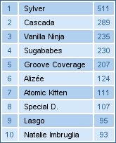
2007-03-01 overall top artist last.fm chart for taw
I'm in a love-hate relationship with Apple products. They are usually cool. But most of the time, they have really stupid design issues that are hardcoded and cannot be fixed by me. One simple example - I cannot tell my iPod to simply forget about the concept of "albums" (it's friggin' trance, not some 1960s music for which people actually cared which album it was on).

One such design screwup is recording, for every song, number of times it was played, and the last time it was played, but not the full log.

And no, the full log wouldn't be too big. By recording song id and time stamp (4+4 bytes) on each play, having iPod running continuously for 10 years, with one song every 3 minutes, the log would still be a mere 14MB. It's hard to get an iPod smaller than 8GB nowadays.

Lack of full log really sucks when it comes to software that coordinates iPods with last.fm. They have two choices:
  • Ignore play count. Sumbit just the last time something was played. Every song is sumbitted just once, even if it was played 1000 times on a loop.
  • Add fake entries, so that every song is sumbitted exactly the right number of times.

I modified my iPod-last.fm bridge to give user a choice which way they prefer. The default is still going to be the former option - exact timing, bad statistics. But personally, I like the latter one - bad timing, exact statistics, way more.

I think it's not exactly how last.fm clients are supposed to behave, but it needs explicit user switch, and it results in better charts. And what's last.fm really about if not accurate pretty charts ? ;-)

Just grab the new version of iPod-last.fm bridge, and set $add_fake_songs_to_make_playcount_match in config.rb whichever way you feel.