The best kittens, technology, and video games blog in the world.

Showing posts with label blinkenlights. Show all posts

Friday, November 11, 2016

Breadboard computer - switch board and diode board

I gave it my first try a few weeks ago, but individual resistors were really messing with the build.

So I ordered some 1k resistor arrays, and tried again.

Full setup

Here's the full setup - I'm using Raspberry Pi as USB adapter, getting GND and 5V out of it.

Switch board needs both 5V and GND, while diode board only needs ground, as they all light up on positive signal.

7 8-wide cables connect them, which is probably an overkill, but that's how many I could fit.

Diode board

Diode board is made out of 7 identical 8-bit parts. From bottom up:
  • 8-bit signal input cable
  • 8 diodes (colors rotating between red, green, yellow depending on group)
  • 8-way 1k resistor array
  • Ground

Diodes were a bit too big to fit in line, but they actually look a bit better zig-zagging odd/even.

I'm quite happy with this board.

Switch board

This is somewhat awkward build. There are also 7 identical 8-bit parts. From bottom up:
  • 5V
  • A lot of cabling to get it all together - I really hate this part of the build as it makes everything super awkward just to do something as simple as connecting a bunch of pins together. One upside of soldering is that this kind of connections are super trivial to do.
  • 8-bit on/off switch
  • 8-bit signal output signal cable
  • 8-way 1k resistor array
  • Ground


So when the switch is off, output is connected to 1k resistor to the Ground.
And when the switch in on, output is connected directly to 5V.

There are quite a few problems with this board.

Max power dissipation here is rather large, with 56 wires of 1k resistance each, that's equivalent of just 18ohm, so that's 280mA or 1.4W just for one board. Using PC power supply that would be totally fine, but USB max power supply is just 500mA or 2.5W, so we're already stretching it.

The most obvious solution would be to put much higher resistance, and fancier way would be to do so on both 5V and GND, and then use another board with a drivers for output (like 74HC4050).

Another big problem is that switches are very hard to access - I basically need to use tweezers to flip them. The whole block of cabling on the bottom is extremely silly for what's basically "connect everything with everything" functionality.

Even if that got fixed, inserting input/output cables is fairly awkward compared to my old (soldering-based) solution which used 40-wire IDE socket.

Next steps

I could definitely improve these boards, but they ought to be good enough for now. Next step would be figuring out a way to interact with Raspberry Pi - I want it to be able to read signals from my switches and to send output to diodes.

Raspberry Pi doesn't have anywhere near enough pins for it, so I might need some shift registers or other such chips to widen the interface.

Monday, October 31, 2016

Breadboard computer - experimenting with switch board


I got my first delivery of parts, and I wanted to try testing if breadboard is a viable alternative to soldering, starting with switch board. The idea is very simple:

  • power lines on top of the breadboard are connected to +5V
  • power lines on bottom of the beadboard are connected to GND
  • there's direct connection from GND to bottom of every switch, using 8-wire cables
  • there's individual 8-wire cable with output from every line
  • there are individual resistors (I used 220 Ohm) connecting top of every switch with power line
Here's a quick electric diagram of each of eventually 7x8 output lines:
I can already see weakness of this design - I have 56 resistors to connect (7 switches of 8 each), but there's only 50 lines (10 groups of 5 each), which forces connecting them to lines under each other. As resistors have long leads, they end up touching each other, so testing shows that that this is already not working properly.

Possible solutions:

  • get resistors with common terminal (like 8 resistors with common terminal), so that I'd only need 7 connections to power lines, not 56 – that was actually my original idea, and what I used in my original (soldered) design, but I strangely couldn't find any on amazon or other sites
  • cut resistor leads to smaller length – might still not be enough
  • use second board for just resistors, connect them like DIP elements
  • use fewer switches per breadboard to reduce crowding - it will still be awkward due to inconvenient 5-grouping on power lines, but presumably if I only had 5 switches, I could use two 5-groups per 8-switch
There's one more minor issue - on these breadboards power lines are broken in half, so if I connect them I'd only have 93 out of 100 connection points (1 to get power in, 3x2 to connect the lines) and some extra awkward cabling.


The plan right now is to have a working switch board (doesn't necessarily have to be 56-wide, 40-wide would be fine), and a diode-board. These were invaluable debugging tools during my first attempt.

Tuesday, September 27, 2016

Some ideas for building a computer from scratch

Jasper's computer by evhoffman from flickr (CC-SA)
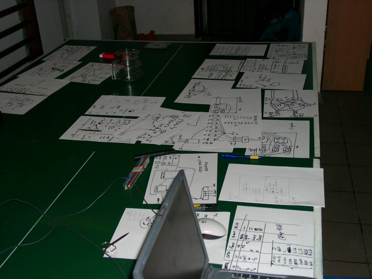
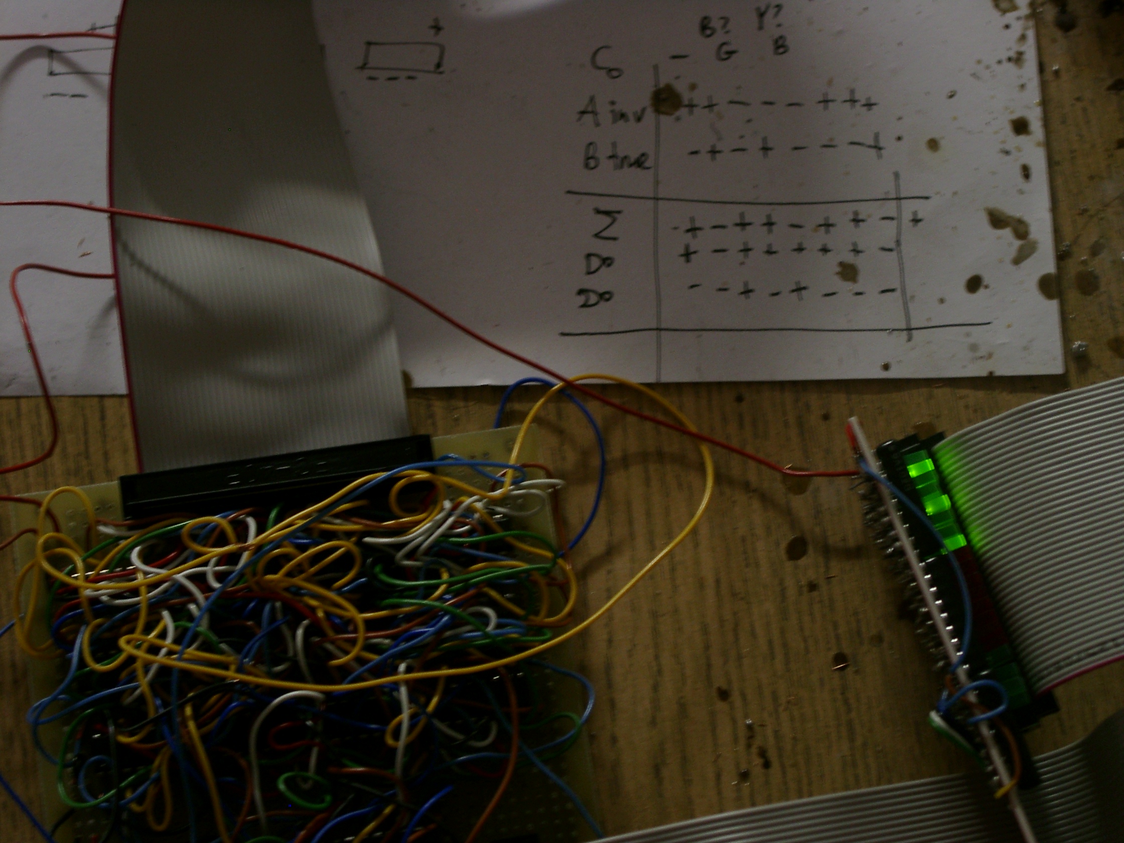
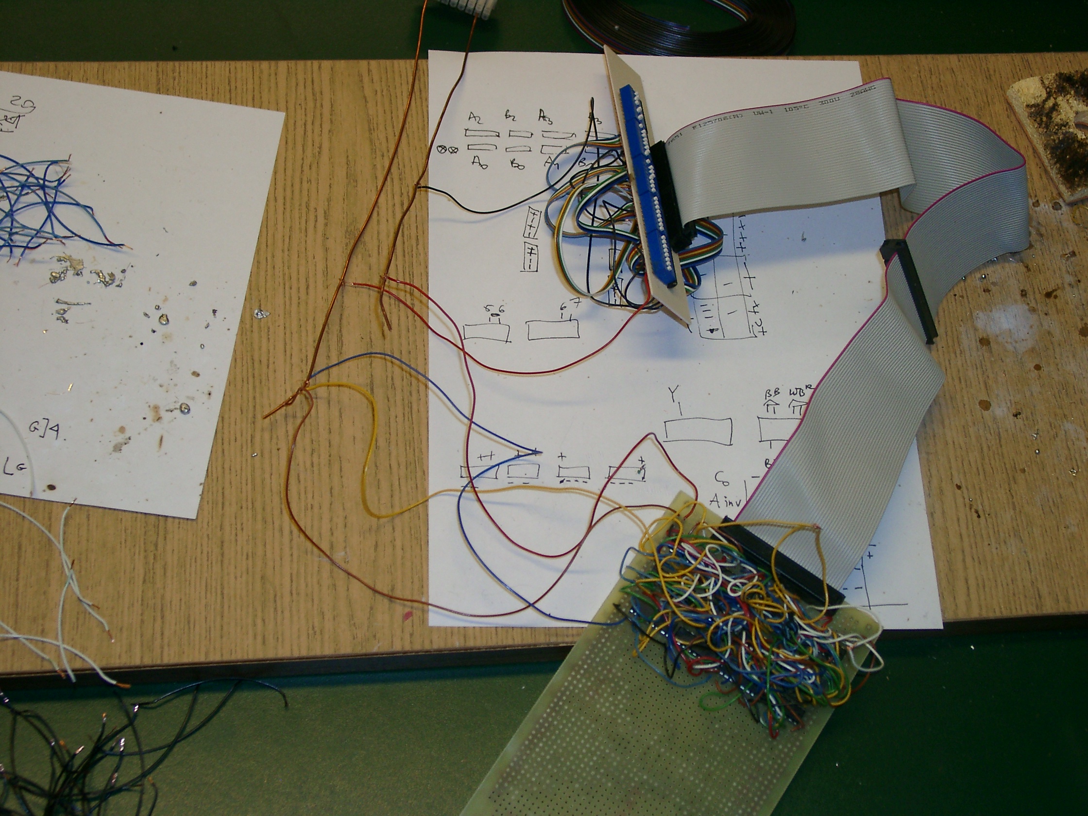
Very long time ago I tried to build a computer from 74LS parts. I didn't get too far, basically I had 40-bit switch input board, 40-bit led output board, and somewhat reasonable ALU.

I had plans to add register file and instruction decoder, and zero clue how to go from there to memory, clock, and I/O - but when I realized how painful soldering has been, and how much worse register file is going to be, I dropped the whole project.

It was still fairly cool way to learn electronics, and you can check the pictures and schematics.

So building entire computer still seems overwhelming, but here's a simpler idea.

Ingredients

  • I could skip soldering completely by just getting a stack of breadboards. It's going to be less compact, and I'll need to setup some kind of frame for them, but anything beats soldering.
  • I wondered about wirewrapping as another alternative to soldering, but nobody uses that.
  • PCBs seem even harder than soldering.
  • 74HC are apparently the new 74LS

Design tools

  • I've heard rumors that there are better languages than Verilog for modelling hardware. It would be nice to investigate one of them.
  • In addition to Verilog-level simulation, I'd like to do some wiring estimations before I start building it
  • Compiler for that architecture shouldn't be too hard to build.

What I actually want to build

  • I want ALU, register file, and instruction decoder
  • some RaspberryPi (or Arduino) will hold memory contents and interface with I/O - it will still need some kind of controller for it
  • Interface between RPi and computer will itself be somewhat complex
  • I'm not sure if I'll have separate clock, or if I'll use RPi as clock source
  • At some point I'd like to get memory - but still every bootup RPi will send contents to that memory before my computer will start running
  • Even if I get memory and clock off-RPi, it will still handle I/O, networking etc. It's nothing unusual, today every disk, every network card, every wifi dongle etc. have tiny computer on board.

Design ideas

  • The fancy multiport register file needs to go as wiring hell, and I can have classic CISC style specialized registers. It doesn't seem like a big difference when you look at Verilog, but there's a reason all old architectures did it this way, and trying to build one taught me that lesson.
  • Completely separate code and data will simplify a lot over shared memory architecture.
  • With separate code vs data, I can make code words as wide as I'd like - it sort of offloads part of decoder duties to compiler.
  • I don't think it will need any fancy microcode, then again any instruction will inevitably take multiple stages. I could start by having extremely wide words, and then moving parts of this logic gradually to instruction decoder.
  • It feels really hard not having 32bits. Maybe going 32bit is reasonable - just making registers wider is simple, ALU won't get any harder (ALU won't do multiply or anything crazy like that, we'll do that in software) except for some zero checks etc., so it's just a matter of wiring all that to memory interface.
  • 32bit architecture would definitely require RPi as controller, Arduino or small 74HC chip just won't have enough memory.

Where to start

  • I think the first step would be to see if Raspberry Pi is a viable memory controller. The RGB LED experiment with software PWM was sort of sanity checking that, but actual memory interface would be much more complicated.
  • If it can run at semi-reasonable speed, I can proceed to designing the rest of the system, and building it part by part. If it doesn't, the whole approach will need rethinking.

Tuesday, September 13, 2016

Adventures with Raspberry Pi: RGB Led Take 2

Once upon a time I tried to do software PWM to set different colors in a RGB Led. It failed.

LEDs are generally either on or off, with no intermediate states - so to get LED at half the intensity, you just turn it fully on for half the time, and blink it fast enough that human eye won't be able to tell the difference.

The problem was that the blinking wasn't fast enough. So now it's time for the long overdue debugging.

First, what the hell is the gem doing? Apparently it's simply writing to files like /sys/class/gpio/gpio17/value. So what if we just write to this file in a loop, skipping the gem? It turns out that's also just not fast enough.

So fallback plan, let's get wiringPi library (git clone git://git.drogon.net/wiringPi) and write it in C:


#include <stdio.h>
#include <wiringPi.h>

int main(int argc, char **argv)
{
  int r = atoi(argv[1]);
  int g = atoi(argv[2]);
  int b = atoi(argv[3]);
  int i;

  printf("Raspberry RGB %d %d %d blink\n", r, g, b);

  if (wiringPiSetup () == -1)
    return 1;

  pinMode(0, OUTPUT); // R
  pinMode(2, OUTPUT); // G
  pinMode(3, OUTPUT); // B

  for (;;)
  {
    digitalWrite(0, rand() % 256 <= r);
    digitalWrite(2, rand() % 256 <= g);
    digitalWrite(3, rand() % 256 <= b);
  }
  return 0;
}

Then compile with gcc -o rgbled rgbled.c -lwiringPi, and run like sudo ./rgbled 255 127 0
And it works!

Now obviously I don't want to write C programs for every trivial thing, so next step would presumably be using ffi interface to wiringPi instead of what PiPiper does with file-based interface.

Thursday, April 23, 2015

Adventures with Raspberry Pi: Weather in London

Welcome to another of my Raspberry Pi adventures.

Previously, I connected raspberry pi to monitor and keyboard and blinked some diodes.

It's time to go a lot further. The first step was removing monitor and keyboard, installing sshd, and just controlling the pi from a regular computer. That leaves two cables - ethernet, and USB power (currently coming from the computer).

I'll replace ethernet with wifi at some point, and reroute power to standalone charger so it doesn't need to be anywhere near the computer.

I also got new multimeter - the old one was totally broken, it wasn't just the battery.


Shift registers

Project for today is driving two 8-segment displays. Even ignoring 8th segment on each which is used for decimal dot (and only really included because 7 segments is a silly number), that's 14 wires. Raspberry Pi presumably has that many usable pins (I'm not entirely sure how many of 40 pins it has can be used for full I/O), but we really don't want to spend out entire pin budget on this.

Instead - we're going to use shift registers. Shift register I use - 74HC595 - has 3 inputs: data, clock, and latch. Whenever clock pin goes from low to high, it reads data pin, pushes data it has left by one, and puts whatever it got in newly emptied bit slot. In 8 such cycles, we can set the whole 8 bit register, one bit at a time.

While we're sending the register data, it is temporarily in inconsistent state, with mix of old and new data. To make sure that's never output, there's a separate latch pin - whenever it goes from low to high, register snapshots its state, and keeps that an the output unless we tell it to get new value.

This way we reduced number of required pins per display from 8 to 3.

74HC595 has a few extra pins (clear, output enable, etc.), but we just hardwire them as we don't rely on that functionality.

Here's a photo of work in progress: data is sent to shift register, and from there to 8-sigment panel, but it's just random bits.


Here's the code:


require "pi_piper"

class ShiftRegister
  attr_reader :data, :clk, :latch
  def initialize(data, clk, latch)
    @data  = data
    @clk   = clk
    @latch = latch
  end

  def out_bit(bit)
    @clk.off
    @data.send(bit == 1 ? :on : :off)
    sleep 0.001
    @clk.on
  end

  def out(byte)
    @latch.off
    byte.each do |bit|
      out_bit(bit)
    end
    sleep 0.001
    @latch.on
  end
end

Eight-Segment Display

Next step is really simple - instead of sending random data telling segments to turn on/off, we want to send it data corresponding to shapes of digits:


The code is really simple:


class EightPanelDisplay < ShiftRegister
  def out_symbol(symbol)
    # DOT, LR, L, LL, UR, U, UL, M
    case symbol
    when "0"
      out [0,1,1,1,1,1,1,0]
    when "1"
      out [0,1,0,0,1,0,0,0]
    when "2"
      out [0,0,1,1,1,1,0,1]
    when "3"
      out [0,1,1,0,1,1,0,1]
    when "4"
      out [0,1,0,0,1,0,1,1]
    when "5"
      out [0,1,1,0,0,1,1,1]
    when "6"
      out [0,1,1,1,0,1,1,1]
    when "7"
      out [0,1,0,0,1,1,0,0]
    when "8"
      out [0,1,1,1,1,1,1,1]
    when "9"
      out [0,1,1,0,1,1,1,1]
    else
      warn "Don't know how to output symbol #{symbol.inspect}"
    end
  end
end

We could even extend that to some simple letters or such symbols - not everything can be distinguished, for example B and 8 will look the same, but it might be useful.

Two digits

So we got down from 2x8 to 2x3 pins. We can do better - we can use same clock and data lines for both shift registers, and only have separate latch pins for each. As registers output whatever was the data inside them at the time they got the most recent rising edge on their latch pin, as long as register's latch pin is steady (doesn't matter even matter if high or low), it doesn't matter what they get on other pins.

There are other ways to connect registers, including daily chaining shift registers so they shift into each other thanks to their extra pins, and we could get away with just 3 instead of 4 raspberry pi pins, but this simple setup is good enough.


 And corresponding code:


pin4  = PiPiper::Pin.new(:pin =>  4, :direction => :out)
pin17 = PiPiper::Pin.new(:pin => 17, :direction => :out)
pin22 = PiPiper::Pin.new(:pin => 22, :direction => :out)
pin27 = PiPiper::Pin.new(:pin => 27, :direction => :out)

register_a = EightPanelDisplay.new(pin4, pin27, pin17)
register_b = EightPanelDisplay.new(pin4, pin27, pin22)

Weather in London

After we had the hardware going, software is really simple - a simple JSON request to OpenWeather API, convert Kelvin to Celsius scale, and send it to our display.

And here's current weather in London, +9C (there's no need for sign, as London never has winters):


And the code:

require "json"
require "open-uri"

url = "http://api.openweathermap.org/data/2.5/weather?q=London,uk"
weather = JSON.parse(open(url).read)

temp_c = weather["main"]["temp"] - 273.15
temp_display = "%02d" % temp_c

register_b.out_symbol temp_display[0]
register_a.out_symbol temp_display[1]

Friday, April 17, 2015

Adventures with Raspberry Pi: basic blinkenlights

Every adventure starts with hello world, and that one took forever.

Here's the setup:
Sunfounder GPIO extension board + breadboard make it so much easier - instead of wiring everything manually I just plug the whole damn thing, and it even has printed pin numbers on the board - Raspberry Pi decided to have insane randomly assigned pin numbers, and then every library for it uses its own different insane randomly assigned pin numbers - I remember back in the days when people numbered pins from 1 to 40 starting in one corner and going clockwise. What the hell happened?

I ran into a lot of annoying issues:
  • My old raspberry Pi (model B+, not 2 B) was not compatible with the kit, so I had to get new one
  • SD card I used for old Pi was of the big kind, so I had to take small one out of my phone instead
  • I needed to install confusingly named ruby1.9.1-dev apt package (which actually contains 1.9.3) before any gems would install.
  • And my voltmeter seems dead, it's probably just batteries, but it uses 9V batteries which I don't have spares for so I won't be able to check that until tomorrow.
  • Why do resistors have to use this ridiculous color coding system instead of just printing damn values as numbers? I get it that back in the 1950s printing numbers would be hard, but come on. Figuring out which resistor is which was pain, and I didn't have voltmeter to test them. (I never learned this damn color coding, as it was way easier to just check them with a meter).
  • It took a few tries to figure out which pin numbering system Pi Piper uses - apparently the same one as is printed on Sunfounder expansion board. That will make it a lot easier.
The first program is:


require "pi_piper"
pin4 = PiPiper::Pin.new(:pin => 4, :direction => :out)
pin17 = PiPiper::Pin.new(:pin => 17, :direction => :out)
loop { pin4.on; pin17.off; sleep 0.25; pin17.on; pin4.off; sleep 0.25 }

Can you guess what it does? No prizes.

It's not much, but with all hardware projects just getting basic hello world typically takes really long time and runs into a lot of annoying problems. Now that's behind me, I might be able to do some cooler stuff.

3D printer adventures and Raspberry Pi adventures will at some point join, but it will take a while.

Wednesday, October 17, 2012

Blinkenlights at London Hackspace

I paid a visit to London Hackspace yesterday hoping to play with laser cutter and 3d printer. And of course due to my luck neither laser cutter nor any of 3d printers they had worked, so I decided to do something else and play with electronics.


That's not terribly complicated, but it's my first ever thing using 555 timer circuit.

Due to power cable shortage I had to use red cable for both Vcc and Gnd, I'm totally aware it goes against the most important thing in circuit design - color coding your cables.

Long time ago I made a somewhat serious attempt at building a computer, but it never got past ALU phase since just wiring all the damn things was taking forever.

Here are some photos:


I'm somewhat tempted to give it another go someday, especially if I can find either how to print PCB or find some other way to deal with wiring, since the wiring was the biggest problem as you can probably see on the photos - elegant schematics turned into Flying Spaghetti Monster.

Anyway, London Hackspace is open for visitors every Tuesday evening, so if you live in London or are just passing by it's a good idea to drop by and see what's there.

I haven't decided if I want to get seriously involved or not, but I plan to at least give it another go - maybe the next time laser cutter and 3d printer will be working, or I'll find someone knowledgeable about PCB etching (since they have etching station over there too).

Actually does anybody know if laser cutter can be used to make PCBs? It sounds like it should since it can make both traces (by cutting a bit into top copper layer) and holes (by cutting all the way through) and with careful positioning it might even be able to do the same to the bottom layer in matching way. It sounds a lot less messy to just cut it with lasers rather than mess with ton of chemicals, but maybe it doesn't really work as well I as hope.

Friday, January 05, 2007

Blinkenlights, part 3 - wires

~How sweet is this? by *Sage* from flickr (CC-NC-ND)
When I started to think about electronics, I didn't spare much thought for the wires. The ICs (integrated circuits), the diodes - they were interesting. But wires ? What could possibly be interesting about them ? And in any case, number of wires is pretty much determined by number of wired elements - something like one wire for each two pins. Anyway, it's boring, boring, boring.

So when I made design decisions for the TTL CPU, I had two criteria:

  • Number of ICs
  • Number of things that can go horribly wrong and fry the ICs

In retrospect, I should have thought about wires too. But let's start with a simple example - a register file read port.

A register file consists of some small amount of memory, and a few ports. There are two kinds of ports. Write ports, that let you write to the memory, and read ports that let you read from the memory. Most register files have 1 write port and 1-3 read ports. For simplicity, let's just design one read port for a straightforward register file.

First - the memory. It's pretty common to simply use 8 8-bit D flip-flops. The read port is going to get the number of port to be read as a 3 bit number.

This means the read port has 64 input wires from memory, 3 input wires for address, and 8 output wires for the data.

But first, some explanations.

A 2-input multiplexer is a device that gets 2 input wires, 1 select wire, and outputs to 1 wire. If select is high, it connects the first input to output. If select is low, it connects the second input to output. Multiplexers are very useful, so they also make ones that can handle more signals. A 4-input multiplexer has 4 input wires, 2 select wires, and 1 output wire. An 8-input multiplexer has 8 input wires, 3 select wires, and 1 output wire. These three are common. Bigger multiplexers or not-power-of-two multiplexers aren't made for practical reasons.

A three-state driver is a device that gets N input wires, 1 enable wire, and N output wires. If enable is high, input and output wires are connected (first input to first output, second to second and so on). If enable is low, input and output is simply disconnected. It's called "three-state" because its outputs can be low, high, or disconnected; not just low and high like in most ICs.

Probably the simplest way of building a read port is using 8 8-input multiplexers (74LS151), one for each input. Each of them gets 3 address wires, 8 input wires (one from each D flip flop), and is directly connected to 1 output wire. So total is 8 chips, 64 (input) + 24 (address) + 8 (output) = 96 wires. And nothing could possibly go wrong - no matter what values are on the wires, the design is not going to fry.

The alternative is based on three-state drivers. We put one 8-input three-state driver (74LS244) after each memory D flip flop chip, and connect all their outputs together to the bus. So first bit of the first driver, with first bit of the second driver, and so on, all go to the first bit of the bus. To convert 3-wire address to 8 enable signals for the drivers we need one more chip - a 3-to-8-decoder (74LS138). Together that's 64 (input) + 11 (address) + 64 (output) = 139 wires. And if for any reason two three-state drivers feel like going active at the same time, the whole box can simply fry.

So to sum it up:
Multiplexers3-state Drivers
ICs89
Wires96139
Safeyesno


So by my reasoning, nobody who is even remotely sane would use three state drivers for a register file read port.

I was wrong.


Let's include one more criterion to the equation - number of pairs of ICs that need to be connected. The address bus and the output bus are counted as devices here.

In multiplexer based solution, each multiplexer is connected to the address bus, 8 D flip-flops and the output bus. So number of connected device pairs is 80.

In three state driver based solution, each three state driver is connected to one D flip-flop, the 3-to-8 decoder, and the output bus. The 3-to-8 decoder is also connected to the address bus. So the total number of connected device pairs is only 25.

In other words, multiplexer-based register file read port is a wiring hell ! I'm more than willing to accept more ICs, more wires, and potential fry-safety issues, just to get decent wiring.

This post was about register files - a bigger, more complex, and more fryable design wins because of much simpler wiring. There's a strikingly similar situation with design of the blinkenlights, and that's the subject of my next post.

See also: part 1, part 2.

Blinkenlights, part 2 - sound cards

~Little Ginger Tabby~ by *Sage* from flickr (CC-NC-ND) Parallel port seems to be the right way to go, but it wasn't my only idea. As a short detour of the real story, here's a bit about another way of communicating with a computer - a sound card. Sound is a pulsation of air. Sound cards have absolutely nothing to do with sounds. What they actually do it converting digital signals from computer to analog voltages on the line (to speakers), and analog voltages on the line (mic) to digital signals for the computer. Conversion between the analog voltage and the "sound" is actually performed by the speakers, headphones, mic, and so on. Of course there's absolutely no reason for plugging only sound devices into sound card ports. Long time ago I tried to make computers talk with each other, by plugging one's speaker port to other's mic port, and creatively perlscripting (they did have ethernet cards, it was just for fun). I actually expected the numbers send to the sound card and received from the other sound card to be identical, except for some noise and linear scaling factor. It turned out not to be the case. When I sent the sound and played what was received, it was pretty similar, but when I tried to pass arbitrary data, there was hardly any similarity between data sent and data received. I guess there are some low/high-pass filters, and other stuff on the way, good enough for sound, but making it really difficult to use it for anything else. Fast forward to a few years. When I was trying to build some blinkenlights display, before I even thought about the parallel port, my thoughts went to the sound card. The first thing when dealing with any electric device is grabbing a multimeter and verifying what really happens inside. Sound cable has one pin divided into three parts. One is ground, the other two are left and right signal. Using a meter on that is trivial. So I flooded /dev/dsp with various kinds of data, and observed on the multimeter what was happening. First I tried constant data, and DC (direct current) voltage meter. It was almost hopeless, something did happen, and I was able to affect the results, but the relation was very weak and unstable. Then I thought - sound cards are not really for DC, sound is an AC phenomenon, so how about trying some constant-frequency sounds and using AC (alternating current) voltage meter ? In retrospect it seems obvious - but DC is so pervasive in computers, that my mental processes associated AC with "this weird high useless voltage thing that enters the power supply unit, and gets converted to some useful (that is - low voltage DC) kind of power". And it worked - I could reliably control ACV reading using the following snippet of Octave (Octave has nothing to do with sound, it's a numerical computations programme) code:

len=10; freq=50; cycle_per_sec=8000; mV=50
X=[mV*0.55*sin((1:(len*cycle_per_sec))*2*pi*freq/cycle_per_sec)];
playaudio(X)
mV was number of milivolts I was getting on the multimeter, plus minus a couple percent. The most I could reliably get was about 350mV. What does it all mean ? Well, nothing really. It's just distorted low-bandwidth signal in highly inconvenient form (350mV ACV). Sure, if I really felt bored, I could convert ACV to DCV by a simple diode, and increase the voltage to some decent level (5V DCV or 3.3V DCV, depending on family, I need 5V DCV for 74LS), but other interfaces like parallel port seem far more promissing. And that's what I'm going to explore in the next part. See also: Blinkenlights, part 1.

Tuesday, December 26, 2006

Blinkenlights, part 1

Silly Furry Saturday by Buntekuh from flickr (CC-NC-SA) In two days, I'm going to the Chaos Computing Congress. CCC is about two things - computer security, and blinkenlights. I didn't want to be the only person on the whole congress who didn't make any blinkenlights in their live. Well, I did make a 16-bit ALU, and I even attached some diodes to its input and output ports, but they didn't blink, so it doesn't really count. Actually back then I wanted to build a CPU out of simple 74LS TTL parts. When I started I literally (by literally I mean literally) couldn't tell a NAND gate from a NOR gate. It was an awesomely fast way of learning about hardware. Then I learned how to run simulations on Verilog, how to solder stuff together, and how simple CPUs work. It took me ages before I could reliably connect an inverter to a diode. It gradually became easier, and finally I had a pretty decent 16-bit ALU. I didn't go any further, because by that time I already learned more about hardware than anyone can without jeopardazing their sanity. Also, the register file I wanted now seemed way too difficult to actually make. It was about as complex as the ALU when looking only at number of 74LS TTLs used, but it would be a cabling nightmare. There was just no way to do it in reasonable amount of time, and it would be very fragile. A worse problem was that I had absolutely no idea how to connect it to a computer. If I wanted to do anything useful with the CPU, it would need some way of reading and writing data, network access and so on. I wasn't anywhere hardcore enough to build memory controller and ethernet card on my own, so at least at first memory access and network would have to go through a real computer. After it works, I'd give it local memory, but a computer link would still be necessary for internet, loading code etc. So the project got shelved. If you're interested, the design, Verilog files and photos are all available. One thing I did in the mean time was getting a ColdHeat soldering iron. It's way better than traditional soldering irons, it's much safer, and it's very cheap, so there's really no excuse for not getting one if you want to play with hardware. Of course the interesting thing is connection to the computer. It seems that parallel port is exactly what I was looking for. Parallel port contains ground pins, 8 data pins, all operating on TTL-compatible 5V. It really couldn't have been any easier. Parallel ports have some anti-fry protection, but if it fails, the whole motherboard would have to be replaced, so I didn't want to test in on my machine. Instead, I took some old box, burned a Knoppix, and used the following code (run with sudo):

#include <stdio.h>
#include <stdlib.h>
#include <unistd.h>
#include <sys/io.h>
#include <errno.h>
#include <string.h>

int main(int argc, char **argv)
{
    int port = atoi(argv[1]);
    int value = atoi(argv[2]);
    if(ioperm(port, 1, 1)) {
        fprintf(stderr, "Error: cannot access port %d: %s\n", port, strerror(errno));
        return 1;
    }
    outb(value, port);
    return 0;
}
The hardware part is a bit of an overkill. The only thing you need is to cut a parallel cable and take the 8 data wire and any ground wire, ignoring the rest, but I soldered all 25 cables to a board. It was pretty quick, the ColdHeat soldering iron is really cool compared to my old one. I can already tell that the parallel port acts as expected, using a multimeter on pins. The code above indeed changes pins in the expected way. You can see some photos from today. I could already use it for 8-diode blinkenlights, but that would be pretty lame. It should be pretty easy to create some circuit with more diodes, that accepts 8-bit commands. A trivial one would be a bunch of flip flops, 6 bits for address, 1 for value, and 1 for strobe. That would be enough for 32 bits, still not enough. So I really need some sort of address register. The computer would either first send the address, and then data, or the address register would automatically increase by one every time, whatever is more convenient. I'll think about it later, so far it's been a major success.

Thursday, May 18, 2006

Cold Heat

As seen on ThinkGeek, Slashdot and LiveJournal ... I've got myself a Cold Heat soldering iron ^_^. It's supposed to heat itself to the right temperature in 3 seconds, and cool down to room temperature in 3 seconds, and it has some protection against soldering accidents - it won't heat itself up unless two halves of the soldering tip are bridged by some conductor.

Maybe I should resurrect my TTL CPU. It was kinda fun, trying to build a CPU from basic logic gates, unfortunately it was pretty hard without the right hardware. A decent soldering iron it certainly going to help.

If you want to buy such a toy - in Germany or Poland try Conrad Electronics (shipping from ThinkGeek costs more than the item). In Poland Conrad Electronics also sells them on Allegro. In the U.S. I guess it's ThinkGeek.